Introduction
This page provides supplemental information to help with installation and troubleshooting of your SCAD TM series tank monitor. It includes download links for manuals, color diagrams, guidance and an instructional video. This page is not intended to be a full installation procedure, which is detailed in the manuals.
- Determining Firmware Version
- Manual Download
- External Sensor Foil Placement Guide
- Wiring Guide
Float Sensors - Software Setup (video)
- Troubleshooting
Wiring Troubleshooting
Sensor Output Voltages
How to Simulate a Full Tank
Breakout Board - Diagnostic Mode
- Frequently Asked Questions
Determining Firmware Version
Knowing the firmware version of your TM monitor is helpful because it specifies what error code and diagnostic features are included.
SCAD’s original TM monitors did not display the firmware version after being powered on. All other TM monitors display the firmware version as follows: When the monitor is powered on, all lights will cycle through, then turn off, followed by the firmware version, which is determined by counting lights to the left and right of the 1/2 light, which represents the decimal point. For example, three lights to the left of 1/2 and one light to the right is firmware version 3.1.
Instruction Manual Downloads
| Manual Description | |
|---|---|
| TM1 and TM2 monitors (no lights indicating firmware) | download |
| TM1 and TM2 monitors with firmware 3.1. | download |
| TM1 and TM2 monitors with firmware 3.2. | download |
| TM1 and TM2 monitors with firmware 3.3. | download |
| TM1 and TM2 monitors with firmware 3.4. (Note: Most monitors dislplaying 3.4 are 3.45.) | download |
| TM1 and TM2 monitors with firmware 3.45. | download |
| S2R Converter – SCAD Sensor to Resistance | download |
| External Sensor | download |
| Internal Sensor | download |
| SAE 5 to 1-inch NPT Adapter Plate | download |
| Breakout Board (for special troubleshooting) | download |
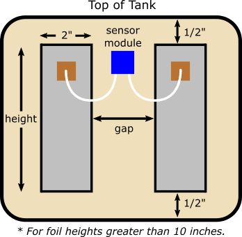
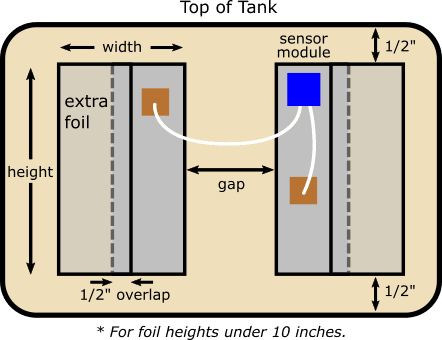
External Sensor Foil Placement Guide
The performance of the external sensor can be optimized by placing the foil strips according to the table below. The external sensors are provided with two inch width aluminum foil tape. When foil height is ten inches or less, the width should be increased. Foil width can be increased by placing additional foil tape toward the outside edges of the two inch strips overlapping by 1/2 inch as in the figure below. For example, an additional two inch strip would result in an overall foil width of 3.5 inches.
Measurements in inches.
| Height | Width | Gap |
|---|---|---|
| 6-8 * | 3-3.5 | 1-1.5 |
| 8-10 | 3 | 1.5-1.75 |
| 10-12 | 2 | 1.5 |
| 12-14 | 2 | 1.75 |
| 14-20 | 2 | 2 |
| 20-24 | 2 | 2.5 |
| >24 | 2 | 2.5-3 |
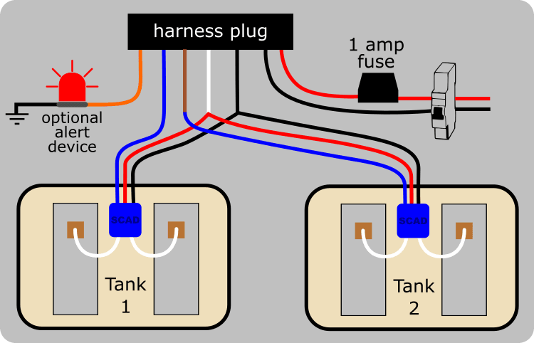
Wiring Guide
We recommend initially wiring the system with wire nuts before committing to butt-splices to verify everything is working first. The figure below is a color illustration of wiring a TM2 to two SCAD external sensors. The white and black wires are split to supply power to the two sensors. The wiring procedure is the same for a TM1 except that there is no brown wire and the white and black wires do not need to be spit. SCAD internal sensors have the same color coded wires as external sensors and are wired the same way.
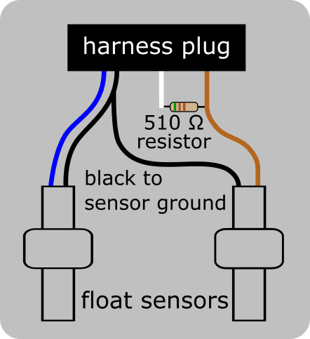
Float Sensors
SCAD TM monitors will read float sensors, which are typically used for fuel. The figure below is a color illustration of wiring for two float sensors. If you want to hook one float sensor to a TM2 monitor, attach it to tank one. A float sensor on tank two requires the addition of a 510 ohm resistor between the white wire and the brown wire. Contact us a call if you need this resistor. Using a float sensor with a TM1 does not require a resistor.
Software Setup (video)
The video below demonstrates the setup and calibration steps for the TM software. The video was created prior to firmware version 3.1 and does not demonstrate the display of the firmware version during the boot up sequence and does not include the diagnostic mode option at the end of the sensor type parameter.
Troubleshooting
We recommend initially wiring the system with wire nuts before committing to butt-splices to verify everything is working first. Troubleshooting is aided by the addition of error codes that are displayed in TM monitors with firmware 3.1 and greater, which is described in the manual.
Wiring Troubleshooting
Monitors with firmware 3.1 and higher will display error codes after attempting to check the level. The error codes are detailed in the manual. The following table provide additional troubleshooting guidance. It assumes that 12 to 14 volts DC is powering the monitor and applies to SCAD internal or external sensors only. Voltage measurements are between the blue sensor wire (+) to the black wire (-) when the monitor is in continuous read mode, which can be entered by touching the pad two times. The monitor pulses power to the sensor, so voltage readings will oscillate from zero to the measured voltage. Note that inexpensive hand held meters may not show a steady voltage when reading the pulsing voltage on the blue wire.
| Symptom | Sensor Light Blinking | Blue Wire Voltage | Possible Problem |
|---|---|---|---|
| Constantly Empty | No | 0 | White harness wire to red sensor wire discontinuous. |
| Constantly Empty | Yes | 0 | Blue wire from sensor to harness discontinuous. |
| Constantly Empty | Yes | 0 | Blue harness wire and black sensor wire shorted. |
| Constantly Full | No | 5.6 | Black wire from sensor to harness discontinuous. |
| Constantly Full | No | 4 | Bue and black wires reversed. |
| Constantly Full | No | 5.6 | White harness wire and red sensor wire reversed. |
| Varies after calibration. | No | 0.7 | White harness wire and blue sensor wire reversed. |
| Monitor gets warm (draws 200mA). | No | 0 | White harness wire and black wire shorted. |
| Monitor gets warm (draws 200mA). | Yes | 6 | Blue harness wire and wire going from white on the harness to red on the sensor are shorted. |
Sensor Output Voltages
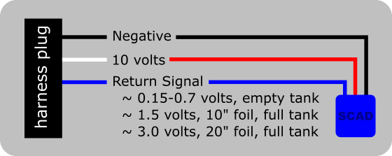
Understanding generally how the TM monitor works is helpful when troubleshooting. When the monitor takes a reading from a SCAD sensor, it momentarily sends 10 volts DC over the white wire to the sensor red wire. In continuous read mode, which is entered by touching the pad twice, the monitor continuously pulses 10 volts. The sensor module at the tank will blink with a blue light when the monitor is in continuous read mode if the white and black wires are terminated correctly. The monitor then reads a returned signal from the blue wire. Monitors with firmware 3.2 and higher include a diagnostic mode, which will display raw sensor signal voltage (see Diagnostic Mode). The values of the return signal can be seen in the figure below for empty and full tanks. Blue wire voltages for tank levels between empty and full are proportional when reading a rectangular tank. These voltages can be read with a conventional volt meter with the negative probe on the black wire. Note that inexpensive hand held meters may not show a steady voltage when reading the pulsing voltage on the blue wire.
How to Simulate a Full Tank
While actual calibration with a full tank is preferable, it is possible to simulate a full tank for rough calibration or testing purposes. This is typically done with the tank empty. The technique requires the the use of at least 1/8 inch thick corrugated cardboard, conventional kitchen aluminum foil, and masking tape or Scotch tape. Cut the cardboard slightly larger than perimeter of both foil sensor strips that are on the tank. Tape the aluminum foil to one side of the cardboard covering the side. Be careful to minimize air gaps and do not overlap the edge of the cardboard. It may be convenient to cut a hole for the sensor module.
To simulate the water, place the cardboard side (not the aluminum file side) tightly over the foil sensor tapes on the tank and tape it in place. Then calibrate the monitor for full. Once calibrated, put the monitor in continuous read mode and move the cardboard up and down to observe whether the level on the monitor changes properly.
Breakout Board for Special Troubleshooting
Most troubleshooting can be can be handled with the advice on this help page, especially with TM monitors that have firmware 3.2 and above because it includes diagnostics for raw voltage readings from the sensor. However, there may be some systems that are difficult for us to diagnose remotely, which is why we created a breakout board. The board plugs into the monitor wire harness and allows easy access to multimeter test points. The manual for the breakout board can be found in the manual download section of this page. These boards are available at the discretion of a SCAD technician.
Diagnostic Mode
When diagnosing errors or inaccurate level sensing, it is helpful to determine what voltage the SCAD sensor signal is returning to the TM monitor. Monitors with firmware 3.2, 3.3 and 3.4 have a diagnostic feature that will display the raw voltage readings from SCAD sensors.
Firmware 3.2 & 3.3
To enter the diagnostic mode, first enter the software setup mode by holding the touchpad until lights illuminate from 1/8 to the 7/8 light and go out. The monitor will then sequence through the first parameter options for sensor type. When the 1/2 option light blinks, touch the pad. The monitor will indicate that it is entering diagnostic mode when it alternates between 3/8 – 5/8 and 1/2 lights for three seconds. Finally, the monitor will display the signal voltage from the sensor according to the list below. To exit diagnostic mode, touch the pad until the monitor returns to normal operation.
- No lights = 0 – 0.003 volts
- Empty = 0.004 – 0.1 volts
- 1/8 = 0.1 to 0.5 volts
- 1/4 = 0.5 to 1.0 volts
- 3/8 = 1.0 to 1.5 volts
- 1/2 = 1.5 to 2.0 volts
- 5/8 = 2.0 to 2.5 volts
- 3/4 = 2.5 to 3.0 volts
- 7/8 = 3.0 to 4.0 volts
- Full = over 4.0 volts
Firmware 3.4
To enter the diagnostic mode, first enter the software setup mode by holding the touchpad until lights illuminate from 1/8 to the 7/8 light and go out. When the 5/8+3/4+7/8 lights flash, touch the pad. The monitor will then display signal sensor voltages using lights to the left and right of the 1/2 light. Lights to the left of the 1/2 indicate voltages to the left of the decimal, and lights to the right indicate 0.2-volt increments. For example, two lights to the left of the 1/2 and three lights to the right represents 2.6 volts.
Frequently Asked Questions
- Does the monitor remember the all settings when the power is off?
Yes. - Why is my wire harness missing a brown wire?
Only TM2 monitors have brown wires. - Which harness black wire is used for power?
The two black wires are common, so it doesn’t matter. - Does it matter if I calibrate empty or full first?
No. But, you must calibrate both in any order. - Why does my monitor always read empty?
The most common cause is that both empty and full were not calibrated.